Physical Network
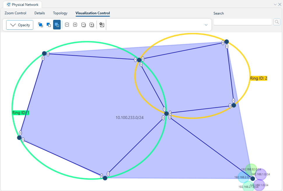
The physical network panel is one of the main ways of visualizing the network in WeConfig, it will render the currently know network topology, including devices, connections between them, subnets and rings. Depicted below is an example topology with a single core subnet and 2 FRNT rings.
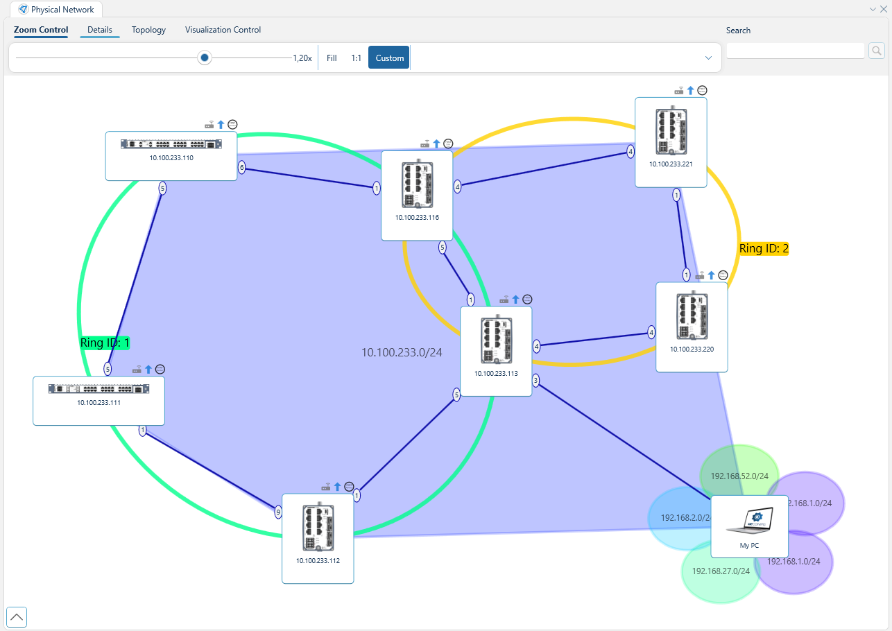
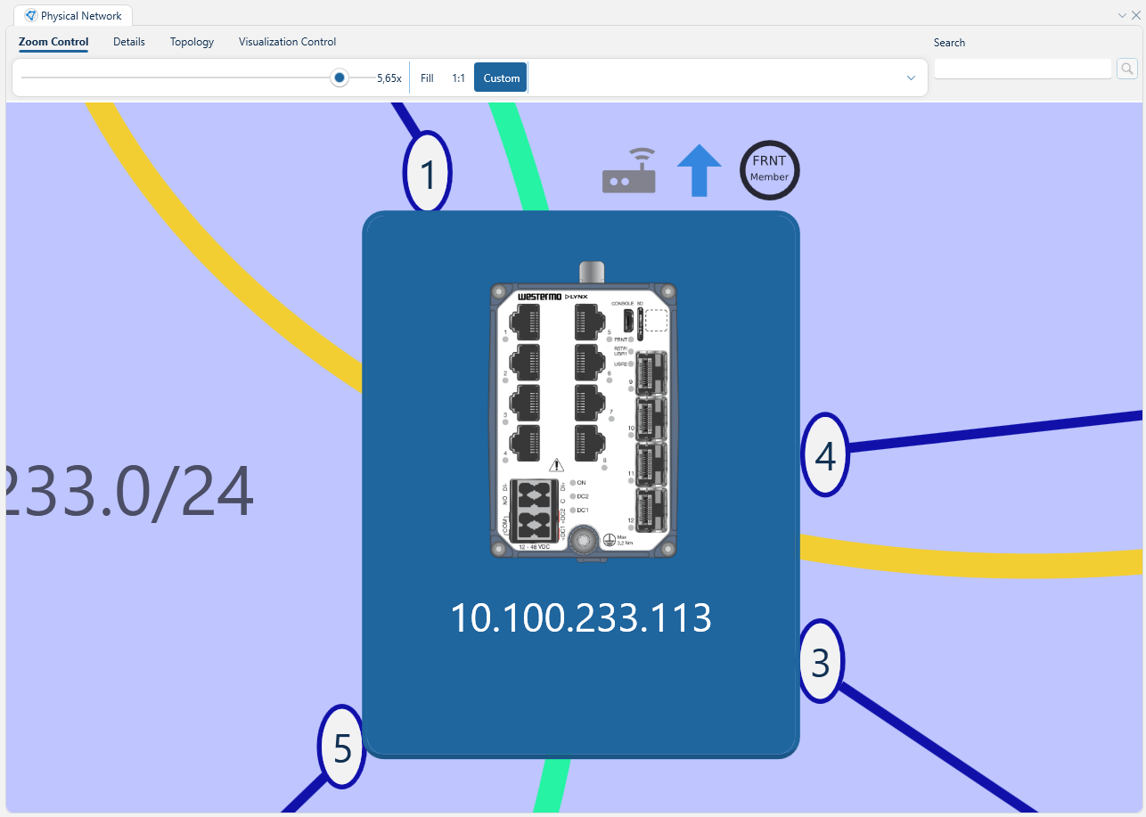
Wherein we can see the 7 different devices (plus the PC). These devices grouped together in the 10.100.233.0/24 subnet indicated by the semi-transparent blue polygon forming between them. We can also observe two rings, Ring ID: 1 depicted in green and Ring ID: 2 depicted in yellow. There are several more components to this topology. Let's zoom in on the device at IP Address 10.100.233.113:
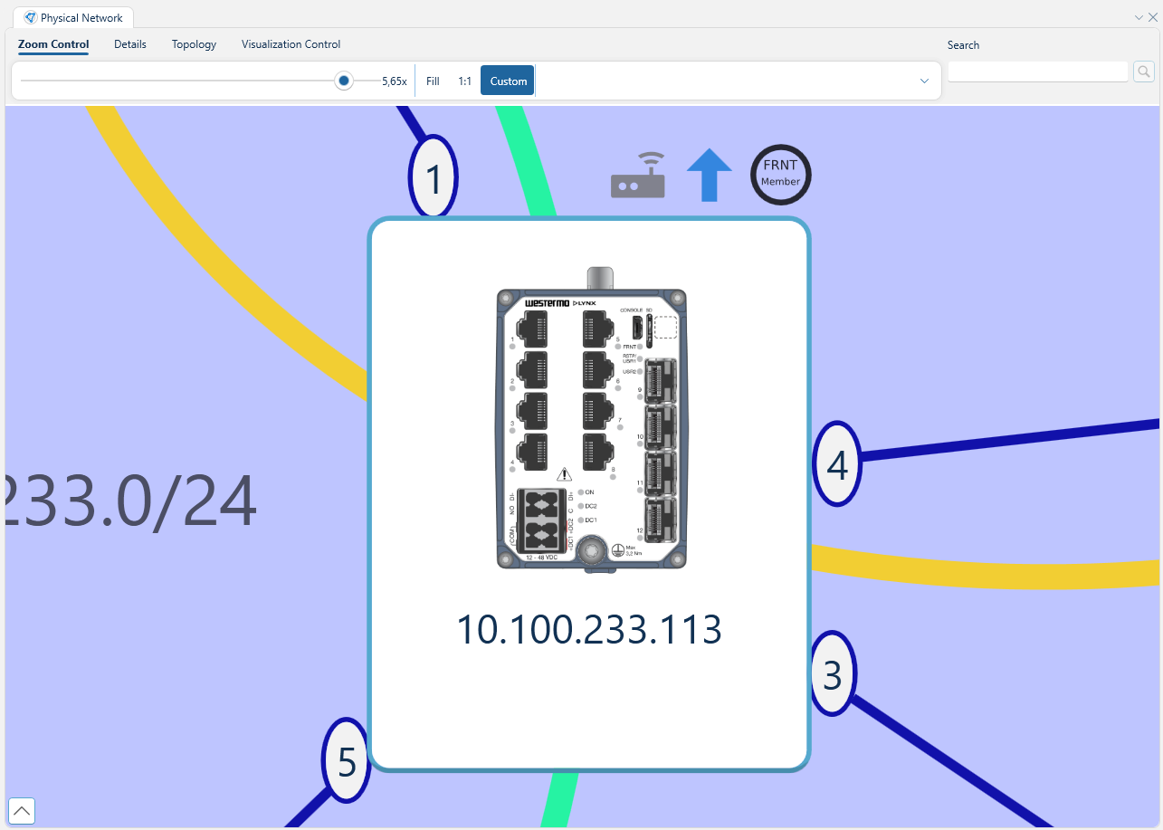
Here we can observe a set of components.
Device border
Within the confines of the device border, there is a picture depicting the device, with its IP address listed beneath.
The contents displayed within the device border can be configured in project settings.
Node Icons
Above the device border, we see a list of icons, 3 in total in this example. These carry information and may serve as quick actions to undertake on the device. See the table below for what each icon means.
| Icon description | Explanation | Clickable |
|---|---|---|
| A box with two dots & signal | Device can act as a router | No |
| Blue up arrow | There is an available firmware upgrade | Yes |
| Blue circle with an 'i' | There is at least one issue linked to this device | Yes |
| A yellow triangle with a '!' inside | Device has connectivity issues. | No |
| A red circle with a '!' inside | Device uses firmware that is not supported | No |
| Circle with "FRNT Member" | Device is part of at least 1 FRNT ring. | No |
| Circle with "FRNT Focal Point" | Device is the focal point for a FRNT ring | No |
| Circle with "MRP Client" | Device is an MRP client | No |
| Circle with "MRP Manager" | Device is an MRP manager | No |
Hovering above each icon also gives additional information about its purpose.
Port labels
Only visible when toggled under the details ribbon, these ellipses on the edge of the device border indicates the port associated with any connections going to and from this device. In the example above, we can see the the device has four connections, one through port 1, one through port 3, one through port 4 and one through port 5.
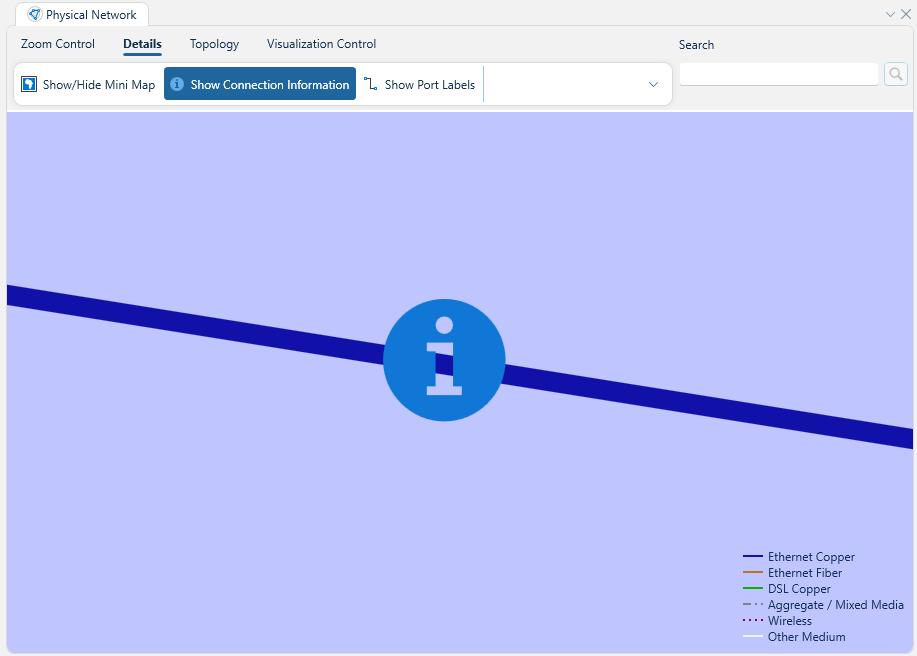
The edge color of these ellipses and their continuation in connection lines also serve to specify the physical medium across which the connection is carried, according to the following table:
| Line | Medium |
|---|---|
| Straight, blue | Copper-based ethernet cable. |
| Straight, orange | Fiber-based ethernet cable. |
| Sinusodal, green | Copper-based DSL cable. |
| Dash-dot-dot, grey | Mixed media / aggregate link |
| Dotted, Purple | Wireless |
| Straight, White/Black | Unknown |
This legend is also available in the topology view itself if "Show connection information" is toggled under the details ribbon
Selection
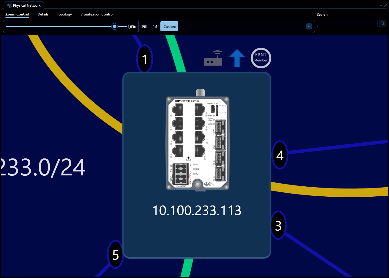
The physical network panel is one of the primary sources of selection in WeConfig, you may select a device by left-clicking on it. Any device that is selected will be highlighted, see image below:

Which depicted the previously mentioned device at 10.100.233.113 when it is selected.
By default, selecting a device deselects any previously selected devices. In order to append to the current selection instead of overriding it, hold down Ctrl while left clicking.
Subnet & Ring Selection
It is possible to select based on both subnets and rings present in the topology as well, to do so, simply click the ring or subnet you wish to select. Some specifications apply for subnet and ring selection:
- Selecting a ring or subnet selects all devices that belong to said ring or subnet.
- A ring or subnet is considered selected if, and only if, all of the devices that belong to said ring or device is selected.
Hovering a subnet or ring will highlight it slightly.
Route visualization
Additionally, whenever a subnet is selected, WeConfig will attempt to visualize its outgoing routes to any other known subnets inside of the topology.

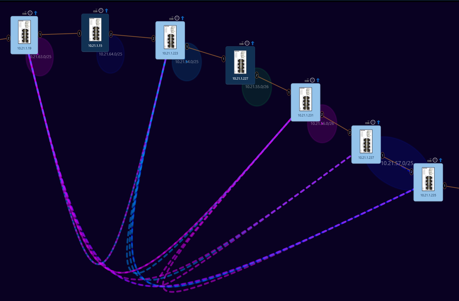
Where we can observe a set of curves going between, for example, the subnet 10.21.63.0/26 and 10.21.54.0/26, with the color indicating the origin subnet and pointing to the target subnet, indicating that route exists from source to target.
Topology control ribbon
At the very top of the physical network panel we will find a ribbon containing a variety of options that allow us to further refine and modify the network topology and how we view it. These are divided into four section, Zoom control, Details, Topology and Visualization control.
Zoom Control


The first ribbon menu controls the zoom level within the physical network topology view. The ribbon contains a slider indicating the current zoom level, as well as a set of three buttons which indicate and alter the current zoom state, they are as follows:
| Button | Purpose |
|---|---|
| Fill | Zoom the network topology to the minimum encompassing bounding box |
| 1:1 | Reset the zoom level to 1 |
| Custom | Does nothing, but indicates that the current zoom state differs from the other options |
The zoom level in the topology can also be controlled via the mouse-wheel.
Details

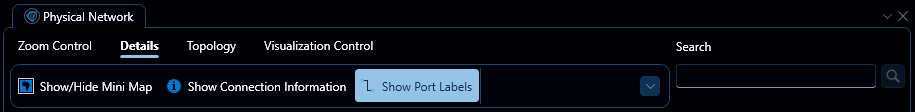
The second ribbon menu controls whether or not certain additional information is rendered, it consists of three toggles, which serve the following purpose:
| Toggle | Purpose |
|---|---|
| Show/Hide Minimap | Controls the display of a network 'Minimap' at the bottom right corner of the panel |
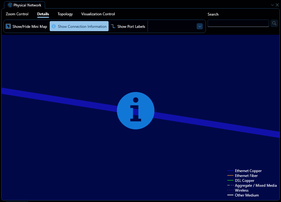
| Show connection information | Controls the display of the connection information legend and the bottom right corner of the panel, as well as the clickable 'Connection Information' buttons that adorn the connections in the topology' |
| Show Port Labels | Controls the display of port labels adjacent to devices |
Connection information
When toggled in the details ribbon, a button will appear on the centre of each connection in the topology, as depicted below:
Clicking this button opens up a connection information flyout, which contains additional information about the connection in question, see one example depicted below:

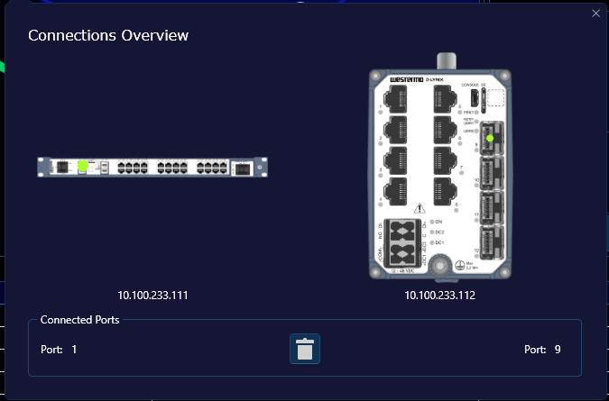
In this example, we can see that the device at 10.100.233.111 is connected to the device at 10.100.233.112 from port 1 to port 9. The device images also indicate the physical location of these respective ports on the device itself with a green dot.
If for some reason, this connection is considered incorrect, the delete button positioned between the port indicators can be used to make WeConfig forget about this connection.
Topology
The third ribbon menu controls the topology layout, it has several options, as depicted below:
Where the options are, from left to right:
| Option | Explanation |
|---|---|
| Lock/Unlock Layout | When toggled, prevents any changes to the topology layout. |
| Auto Layout | Attempt to organize the topology according to the currently set layout algorithm |
| Clear Topology | Removes all devices from the topology. |
| Align Top | Move the Y-coordinate of all selected devices to the Y-coordinate of the topmost selected device. |
| Align Bottom | Move the Y-coordinate of all selected devices to the Y-coordinate of the bottommost selected device. |
| Align Left | Move the X-coordinate of all selected devices to the X-coordinate of the leftmost selected device. |
| Align Right | Move the X-coordinate of all selected devices to the X-coordinate of the rightmost selected device. |
| Distribute Horizontally | Distribute the X-coordinate of the selected devices evenly on a scale between the leftmost and rightmost selected device |
| Distribute vertically | Distribute the Y-coordinate of the selected devices evenly on a scale between the topmost and bottommost device |
| Distribute Radially | Distribute the coordinates of the selected devices evenly in a circle around their average center |
| Flip Horizontally | Invert the X-coordinates of the selected devices around their average X-coordinate |
| Flip Vertically | Invert the Y-coordinates of he selected devices around their average Y-coordinate |
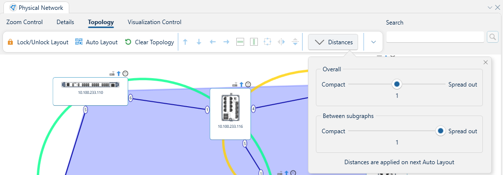
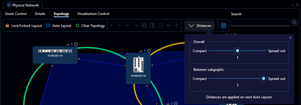
| Distances | Opens a dropdown for controlling the Auto Layout distances. The "Overall" slider controls how far apart devices are placed in general, while the "Between subgraphs" slider controls how far apart disjointed groups of devices are placed. |
Visualization Control
The fourth and final ribbon menu contains additional control over topology visualization, as depicted below:
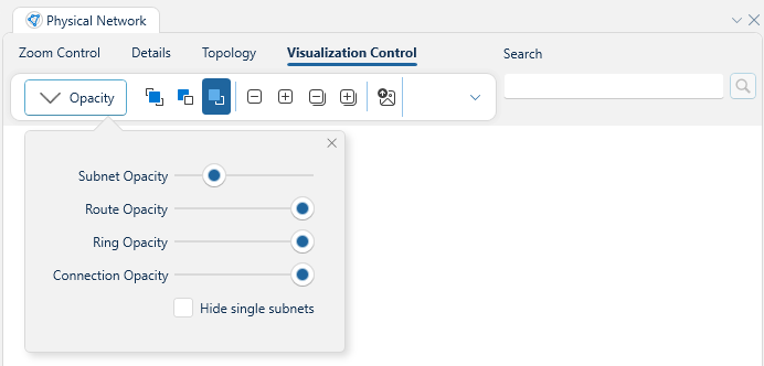
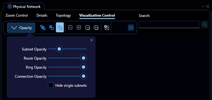
Where the dropdown-menu is toggleable via the "Opacity" button. The dropdown menu allows for control over the opacity of varius topology elements, including subnets, routes, rings and connections. It also has the option to hide subnets that only contain one device. Beyond that, the second set of toggles controls how subnets are colored, with the options being from left to right:
- By subnet address and OSPF area
- By OSPF area
- By subnet address
By default, subnets are colored by their address only.
The next four buttons allow for collapsing and expanding devices. With the first two buttons collapsing and expanding so called "Unknown" devices, or in other words those that WeConfig does not know how to work with, and the last two collapsing and expanding all devices. For example, the original topology depicted at the top of this document would appear like this when all devices are collapsed:

Devices can also be individually expanded or collapsed via the context menu
This allows for a variety of views of the network, for example, if one sets connection opacity to 0 and collapses all devices, one would have as close to a pure "layer 3" view as WeConfig offers today.
Finally, the last button is used to export the current topology as a PNG image.